At Getec Industrial, we are specialists in extruded heat sink solutions that provide better heat sink thermal management. We offer our custom heat sink manufacturing processes using aluminum heat sinks made from 5000, 6000, and 7000 series high-quality aluminum alloys. We have 11 state-of-the-art extrusion presses which enables us to extrude aluminum extrusions in sizes less than 2” up to 20” in diameter to fit any application.
Having thermal issues? Many industries have thermal issues that reduce performance and efficiency. A poor heat sink design can lead to overheating, system failures, and costly downtime. At Getec, we solve these issues with precise custom-engineered heat sink solutions that are designed specifically for your thermal needs.
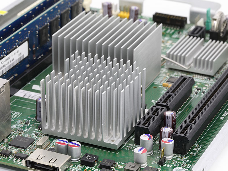
It is important to select the right heat sink design for better thermal efficiency. At Getec, we offer the production of all types of heat sinks for optimal heat transfer with minimal power consumption. If you are looking for an extruded heat sink with a high aspect ratio of fins or an aluminum heat sink for compact designs, we have the perfect solution for you.

Your time is valuable, and so is your budget. Most heat sink manufacturers use third-party die makers which slow down the production process and can cause changes in design.
At Getec:
✅ We extrude heat sink extrusions in-house which means no unnecessary delays.
✅ If adjustments are needed, we modify our dies on-site, not relying on some third-party manufacturer to do it.
✅ Our method of working is more efficient which means that you get high-performing thermal management products faster and at a lower cost than your competitors.
We don’t just build thermal management products—we design solutions that address actual issues. Many industries including aerospace, telecommunications, LED lighting, medical, and power supply depend on our custom heat sinks for improved efficiency and service life.
Don’t let heat management issues slow you down! Whether you need a high-performance custom heat sink or a precision-engineered extruded heat sink, Getec Industrial is your trusted partner in heat sink thermal management.
📞 Call us today: 888-999-8499
📧 Email us: sales@getecna.com
🔗 Get a Free Quote: Fill out our online contact form and let’s create the perfect thermal management system for your needs!